| AutoFEM Analysis Shaft with the Wheel Loaded with the Torque that linearly | |||||||
| AutoFEM Analysis Shaft with the Wheel Loaded with the Torque that linearly | |||||||
Shaft with a Wheel Loaded with Torque Linearly Increasing to a Constant Value
Let us consider Let us review the study of torsional oscillation of steel shaft on the end of which the wheel is attached. The left end of the shaft is fixed. The wheel is attached to the right end.
|
A couple of torsional forces is applied to the shaft from the point in time t=0. The torque of the torsional forces changes under the law:
M(t)=M0(t/T) for t<T; and =M0 for t≥T, where M0=1 kNm, T=0.5E-003 sec.
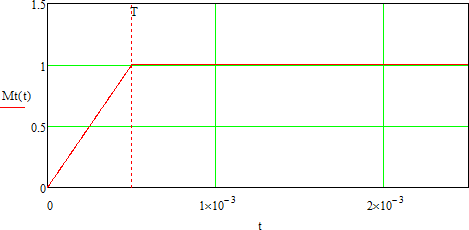
Graph of torque of the forces couple from the time
It is necessary to find the maximum torsion angle and the maximum shearing stresses in the shaft.
Shaft length l=1 m. Cross-section is annular with inner diameter d1=50 mm and outer diameter d2= 80 mm. The wheel diameter is D = 200 mm and its thickness h = 30 mm. The wheel and the shaft have the same material. Modulus of elasticity E=200 GPa, Poisson ratio ν=0.29, density ρ=7900 kg/m3. Amplitude and frequency of external force are correspondingly equal P0=1 kN and ν0=ω/2π=200Hz.
First, it is necessary to find normal basis function - eigenfunctions of the free oscillations of the shaft with the wheel task:
First of all, it is necessary to find normal basis function - eigenfunctions of the free oscillations of the shaft with the wheel task:
![]()
where
![]() - shear modulus;
- shear modulus;
μn- positive roots of the equation:
![]() ,
, ![]() - a polar moment of inertia of the shaft section;
- a polar moment of inertia of the shaft section;
![]() - wheel moment of inertia.
- wheel moment of inertia.
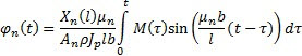
Then the angle of rotation of the shaft is recorded in normal coordinates:
![]()
Then the Lagrange equations are formulated. After their calculation the normal coordinates are defined:
where
![]() .
.
The maximal shearing stress in the section (appears on the outer circumference) is calculated using the formula:
![]()
It is positive if its torque is directed counter-clockwise from the outer normal line side.
Let us limit ourselves by ten terms of series. With the given parameters, the maximal angle of rotation is on the shaft end with the wheel and is 7.326E-003 rad.
The graph of rotation angles of sections with coordinates x=l (shaft end with the wheel) x=0.5l, and x=0.25 l according to the time t.
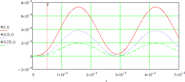
Graphs of angles of rotation of four sections according to the time
Let us create graphs of maximal shearing stresses in the section for three sections with coordinates: x=0 (fixation), x=0.5l and x=l (shaft end with the wheel) according to the t time.
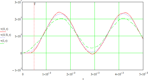
Graphs of maximal shearing stresses in the section according to the time.
Let us calculate AutoFEM Analysis study: We create two studies, one Transitional processes, another Mode superposition with the same loads and restraints.
|
The finite element model with applied loads and restraints |
We create a full restraint on the left butt end of the shaft. The right end will stay free. To exclude the shaft bending we set kinematic restrictions on the radial displacements (radial restrictions are equal to zero) for the outer and inner cylindrical surfaces- for that purpose we apply partial restraints in the cylindrical coordinate system. Displacements by radius and axis are restricted, displacements around the circumference are permitted, Z axis of the cylindrical coordinate system is directed along the shaft axis. On the free end we apply torque load, the value of the load is specified using graph:
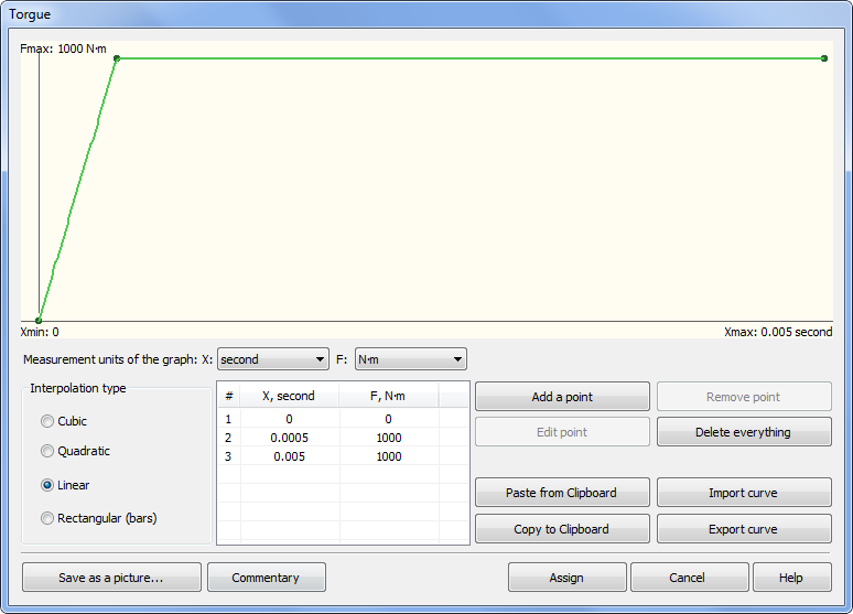
Load graph
For both of the studies, we set the finite modeling time 0,02 s, the time step of integration 1∙10-5 s. The method of time integration: Newmark. We set a number of the lower natural frequencies in the Mode superposition study: 15.
The angle of rotation of the section on the free end of the shaft is calculated by the formula φ=2uyB/d2, where uyB - projection of point B displacement on the 0 y-axis (found from the calculation in AutoFEM Analysis).
On the figure below, you may see the dependences graphs of free shaft end angle of rotation from time for an analytical solution, a numerical solution using Transitional process and Mode superposition.
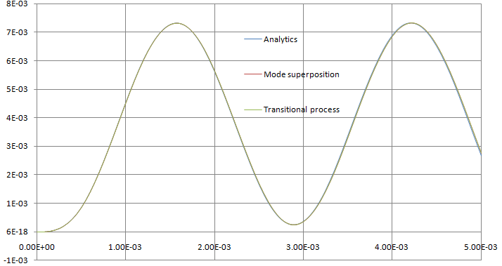
Graphs of rotation angle of free shaft end using analytical solution and solutions by two AutoFEM methods
On the figure below, the difference between analytical solution and solutions by two AutoFEM Analysis methods are shown.
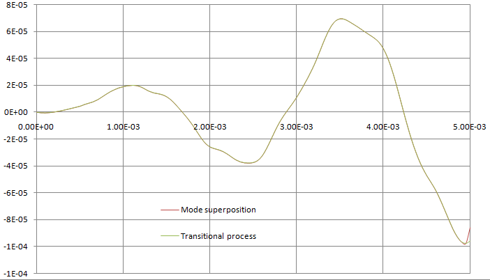
Graphs of differences of rotation angle of shaft end using analytical solution and solutions by two AutoFEM methods
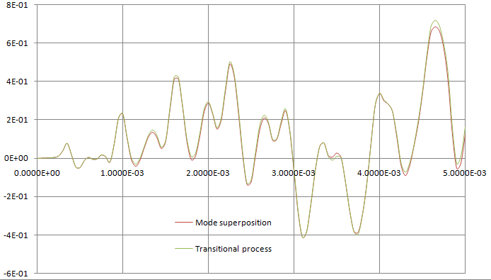
On the figure below, the graphs of shearing stress τxy in the point A using analytical solution and numerical solutions by two methods in AutoFEM Analysis are shown. Positive directions of the shearing stress of analytical solution τA and considered in the theory of elasticity τxyA (by AutoFEM Analysis) are shown on the figure “The finite element model with applied loads and restraints”.
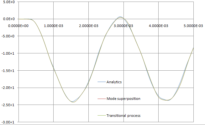
The graphs of shearing stress in the point A using analytical solution and two numerical solutions by two methods in AutoFEM Analysis are shown.
On the figure below, the graphs of shearing stress differences τxy in the point A using analytical solution and numerical solutions by two methods in AutoFEM Analysis are shown.
The graphs of shearing stress differences in the point A using analytical solution and two numerical solutions by two methods in AutoFEM Analysis are shown.
After carrying out calculation with the help of AutoFEM, the following results are obtained:
Table 1.Parameters of the finite element mesh
Finite Element Type |
Number of Nodes |
Number of Finite Elements |
quadratic tetrahedron |
1858 |
5483 |
Table 2.Parameters of temporal discretization
Total calculation time (s) |
Time step (s) |
Number of time layers |
0.04 |
2.5E-005 |
1601 |
Table 3. Transitional processes, maximal torsion angle*
Numerical Solution |
Analytical Solution |
Error δ =100% (φ* - φ) / φ |
7.3173E-03 |
7.326E-003 |
0.1 |
Table 4. Mode superposition, maximal torsion angle*
Numerical Solution |
Analytical Solution |
Error δ =100% (φ* - φ) / φ |
7.373E-03 |
7.326E-003 |
0.1 |
Table 5. Transitional processes, maximal shearing stress*
Numerical Solution |
Analytical Solution |
Error δ =100% (τ* - τ) / τ |
24.258 |
24.0 |
1.0 |
Table 6. Mode superposition, maximal shearing stress*
Numerical Solution |
Analytical Solution |
Error δ =100% (τ* - τ) / τ |
24.249 |
24.0 |
1.0 |
Conclusions:
The maximal angle of rotation of shaft free end calculated using AutoFEM Analysis is: for the Transitional process 7.373E-003 rad (relative error 0.1%), for the Mode superposition 7.373E-003 rad (relative error 0.1%). The maximum shearing stress at the A point found using AutoFEM Analysis is: for the Transitional process 24.258 MPa (relative error 1.0%), for the Mode superposition 24.249 MPa (relative error 1.0%).
*The results of numerical tests depend on the finite element mesh and may differ slightly from those given in the table.
Read more about AutoFEM Static Analysis

