| AutoFEM Analysis Buckling Analysis of a Compressed Tube (surface) | |||||||
| AutoFEM Analysis Buckling Analysis of a Compressed Tube (surface) | |||||||
Buckling Analysis of a Compressed Straight Tube (surface)
Let's review the buckling analysis of a straight tube compressed with an pressure q. The tube has length L, middle radius R and wall thickness h, both ends being simply supported. Sought is the load factor corresponding to numbers of half-waves n,m of the tube buckling. Assume the beam length equal to 1 m, and the crosssection dimensions R = 0.056 m, h = 0.006 m.
|
Material characteristics assume default values: Young's modulus E = 2.1E+011 Pа, Poisson's ratio ν = 0.28.
Let's define the boundary conditions as follows. The up and bottom faces are restrained in XY-axes, the bottom face is additionally fully restrained at a point; outer surface is subjected to the pressure load in the amount of 1 Pa.
Analytical solution:
![]()
![]()
Solution is sought for n,m = (2,1); (2,2).
|
The finite element model with applied loads and restraints |
After carrying out calculation with the help of AutoFEM, the following results are obtained:
Table 1. Parameters of finite element mesh
Finite Element Type |
Number of nodes |
Number of finite elements |
linear triangle |
3636 |
7200 |
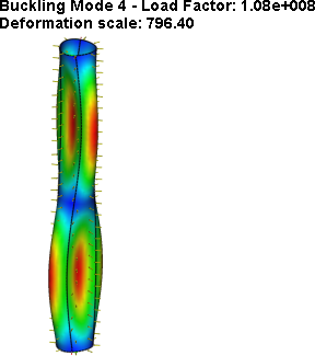
Table 2. Result "Critical load"*
Numerical solution |
Analytical solution |
Error δ = 100% *|P*critical-Pcritical| / |Pcritical| |
9.5702E+007 |
9.5204E+007 |
0.52 |
1.0796E+008 |
1.0436E+008 |
3.45 |
|
|
*The results of numerical tests depend on the finite element mesh and may differ slightly from those given in the table.
Read more about AutoFEM Buckling Analysis