| AutoFEM Analysis Forced Oscillation of a Simply Supported Plate | |||||||
| AutoFEM Analysis Forced Oscillation of a Simply Supported Plate | |||||||
Forced Oscillation of a Simply Supported Plate
Let us consider a simply supported plate loaded with harmonic force (see figure).

The force applied at distance c varies with time by harmonic law:
P(t)=P0sin(ωft),
where P0 is equal to 125 N.
ωf= 2π ff ,
where the frequency ff ranges from 4Hz to 32Hz.
Our aim is to find oscillation amplitudes of a point with coordinate x using the specified frequencies.
Let us use the following initial data: length of the plate L = 850 mm, the cross section is a rectangle with width b = 75 mm, height h = 5 mm. Harmonic force is applied at a point with x=Lp=0.5L=425 mm.
Parameters of the material: modulus of elasticity E=2.1E+011Pa, Poisson's ratio ν=0.28, density γ=7800kg/m3.
Classic analytical solving
Natural (resonant) frequencies of the system are:
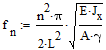
f1,2,3,4= 16.2826; 65.1304; 146.5434; 260.5216. Thus, first natural frequency falls in range 4Hz to 32Hz.
Static deflection at point x is calculated by formula (retaining 15 terms in a sum):
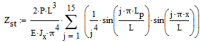
Where Jx=bh3/12 - the moment of inertia of cross-section.
Thus, deformation under the static load ΔZst = 9.747628 mm.
Dynamic deflection at point x is calculated by formula (retaining 15 terms in a sum):
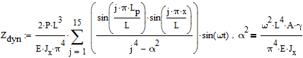
Maximum deformation is attained at ωt=π/2. Deflection under the dynamic load at 4Hz to 32Hz: ΔZdyn = 10.364731; 12.805064; 21.169956; 279.32888; -18.741249; -8.049125; -4.763555; -3.20966 mm.
Numerical solution
Let us solve this study by AutoFEM Analysis package. Both ends are restrained to simulate simple support: displacements of the left end along XYZ-axis are forbidden and rotation only around Y-axis is allowed; displacements of the right end along YZ-axis are forbidden and rotation only around Y-axis is allowed.
|
The finite element model with applied loads and restraints |
The static displacement of the system is ΔZ*st = 9.7570 mm (the result "Displacement OZ" of the study "Study 1 (Static Analysis)").
First eigenfrequency is equal to f(1)n =16.291 Hz (the result "Mode 01 (16.291 Hz)" of the study "Study 2 (Frequency Analysis)").
Vibrational amplitudes have the following values: Z*dyn= see table 2 (results "4.000 Hz Displacement OZ ... 32.000 Hz Displacement OZ" of the study "Study 3 (Forced Oscillations)").
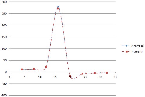
Let us compare the results of calculation:
Table 1. Parameters of the finite element mesh
Finite element type |
Number of nodes |
Number of finite elements |
linear triangle |
585 |
256 |
Table 2. The results
Frequency ff , Hz |
Analytical solution |
Numerical solution |
Error δ = 100* | R* - R | / | R |, % |
0 |
9.7570 |
9.7704 |
0.14 |
4 |
10.3739 |
10.3747 |
0.01 |
8 |
12.8125 |
12.8143 |
0.01 |
12 |
21.1616 |
21.1684 |
0.03 |
16 |
271.3779 |
272.9463 |
0.57 |
20 |
-18.8152 |
-18.8049 |
0.05 |
24 |
-8.0705 |
-8.0679 |
0.03 |
28 |
-4.7739 |
-4.7727 |
0.03 |
32 |
-3.2156 |
-3.2150 |
0.02 |
|
*The results of numerical tests depend on the finite element mesh and may differ slightly from those given in the table.
** The negative signs are applied inversely, because Z-axis of results is directed up.
Read more about AutoFEM Oscillations Analysis

