| AutoFEM Analysis Bending a Cantilevered Beam under a Concentrated Load | |||||||
| AutoFEM Analysis Bending a Cantilevered Beam under a Concentrated Load | |||||||
Bending a Cantilever Beam under a Concentrated Load
Let us consider a cantilevered beam of length L, loaded with the force P at the right-hand end. The beam cross-section is a rectangle of width b and height h.
|
Sought is the maximum beam deflection.
Assume P = 825 N, L = 0.5 m, b = 0.05 m, h = 0.02 m.
Material characteristics assume default values: the Young's modulus E = 2.1E+011 Pa, Poisson's ratio ν = 0.28.
The left-hand end of the beam is fixed, and the right-hand end is subjected to the load amount P, directed vertically downward.
|
The finite element model with applied loads and restraints |
The analytical solution appears as:
w = ( P . L3 ) / ( 3 . E . J ) = 4.9107E-003 m
where P – is the force, L – the beam length, E – the material Young's modulus, J = b . h3 / 12 - the moment of inertia.
After carrying out calculation with the help of AutoFEM, the following results are obtained:
Table 1.Parameters of the finite element mesh
Finite Element Type |
Number of Nodes |
Number of Finite Elements |
quadratic tetrahedron |
1017 |
3593 |
Table 2. Result "Displacement, magnitude"*
Numerical Solution |
Analytical Solution |
Error δ =100%* |w* - w| / |w| |
4.8792E-003 |
4.9107E-003 |
0.64 |
|
|
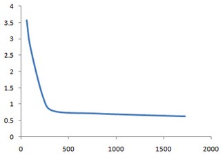
Dependence of the relative error on the number of finite elements |
Conclusions:
The relative error of the numerical solution compared to the analytical solution is equal to 0.64% for quadratic finite elements.
*The results of numerical tests depend on the finite element mesh and may differ slightly from those given in the table.
Read more about AutoFEM Static Analysis