AutoFEM Harmonic Forced Oscillations Analysis
Analysis of forced oscillations is performed to predict the behaviour of a structure under external actions which change in accordance with the harmonic law. These actions include force and/or kinematic excitation. In addition to it, the impact of the system damping may be taken into account.

Forced Harmonic Oscillations Analysis
The objective of the forced oscillation analysis is to obtain a dependence of the system’s response on frequency of compelling actions. As a result of calculations we get amplitudes of displacements, vibration acceleration, and vibration overload at the preset compelling frequency. According to these results, one can obtain, for a frequency range, the dependencies of amplitudes and vibration acceleration on frequency of compelling actions, which is important with the evaluation of vibration stability of the system in this preset frequency range.

Phase control of the result
The rotation of a shaft or spindle in the unbalanced state on elastic supports may serve an example of external harmonic force. Kinematic excitation is applied when values of compelling forces are not known, in contrast to amplitudes of oscillations of some structure elements which are known.

Graph of the amplitude-frequency response of the structure
When considering forced oscillations, it is important to take into account the impact of damping forces. The process of energy dissipation of mechanic oscillations, leading to step-by-step attenuation of lump-sum produced oscillations of the system, is termed “damping”. Damping forces may have different origin, namely: friction between dry sliding surfaces, friction between lubricated surfaces, internal friction, air or liquid resistance, etc. It is usually presumed that the damping force is proportional to velocity (viscous damping). Resistance forces changing under the voluntary law are replaced for equivalent damping forces, proceeding from the condition that in one cycle, they dissipate the same amount of energy as real forces.
Dialog of Study's properties
The main results of calculation in the module of forced oscillations are the following values:
- Amplitudes of displacement at finite element mesh nodes Um.
- Vibro accelerations at finite element mesh nodes expressed via amplitudes Um as.
- Vibro overloads, defined as the ratio of vibro acceleration to free fall acceleration.
Below you can find some examples of AutoFEM Forced Oscillations Analysis
|
Verification Examples of AutoFEM Forced Harmonic Oscillations Analysis |
|
|
|
|
|
|
Vibrations of the spring-mass system because of oscillating foundation |
Quick Start (Tutorial) on AutoFEM Forced Oscillations Analysis
Welcome!
This lesson will help you to perform the forced oscillation analysis by the AutoFEM Analysis package.
You will learn to : create a Forced Oscillation Analysis study;
 create the finite element mesh;
 specify a material;
 specify loads and constraints;
 obtain calculation results in the form of colour plots.
Download tutorial video of the AutoFEM Oscillation Analysis Module
Create Forced Oscillation Analysis Study
Step 1: Create Forced Oscillation Analysis Study
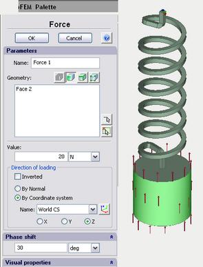
Let us consider the mass- spring system (see figure). The plummet is subjected to a harmonic exciting force with amplitude of20 N and phase shift of 30 deg.
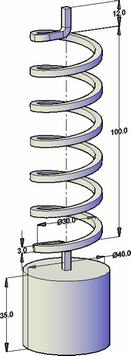
It is necessary to calculate oscillation amplitudes of the mass and phase shifts of the system, using the frequencies, which ranges from 5Hz to 30Hz. The ratios of the Rayleigh damping have following values: ?= 0.02, ?= 3E-004. These values correspond to ~2% of the critical resistance.
To create the Forced Oscillation Analysis problem, we should:
1.Invoke the New problem's properties window using one of the following methods:
|
Command Line: |
FEMASTUDY |
|
Main Menu: |
AutoFEM | Create a Study... |
|
Icon: |
|

2.Select the type of the study ( "Forced Oscillation" ) and add to the list ( "Selected Geometry" ) a solid;
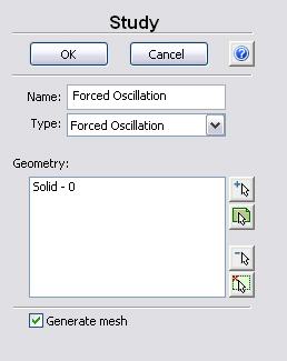
3.Since the option "Generate mesh" is activated, after setting up the problem, the system will automatically proceed to creating finite element mesh;
4". Press  to confirm the New problem creation.
Create Finite Element Mesh
Step 2: Create Finite Element Mesh
After the problem setup, the system automatically proceeds to creating finite element mesh.
To create manually (or modify) the finite element mesh, we need to carry out the following sequence of steps:
1.Invoke the Mesh's properties window by one of the following methods:
|
Command Line: |
FEMAMESH |
|
Main Menu: |
AutoFEM | Create Mesh... |
|
Icon: |
|

2.Let us build the finite-element mesh. The mesh quality is 2, the curvature is 24", the edge length of an element will be no greater than 5.000 mm.
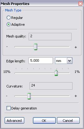
3. Press to complete creating (or modifying) the mesh.
The result of mesh generation is displayed in the 3D window.
Instead of the original model, now you will see the image of the mesh. The original model is not shown at that moment.
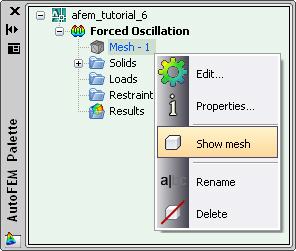
In case it is necessary to hide or display again the finite element mesh, choose the element "Mesh" in the service window "AutoFEM Palette" , then invoke the command "Hide Mesh" or "Show Mesh" from the context menu (by pressing  ).
).
Specify Material
Step 3: Specify the Material
For each problem of the finite element analysis, it is important to correctly specify characteristics of the part's material.
To specify (or modify) the material, we need to carry out the following sequence of steps:
1.Invoke the material's properties window by choosing the folder "Solids" in the service window "AutoFEM Palette" and performing the command "Material..."from the context menu (by pressing  ).
).
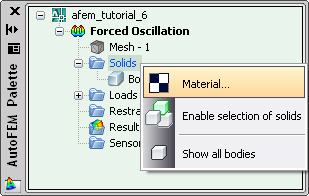
2.Provide a library of materials (into the group "Library");
3.From the list of materials select the material "Plain Carbon Steel" .
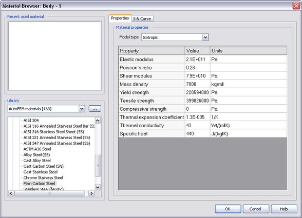
4.Confirm your selection by pressing .
Apply Restraints
Step 4: Apply Restraints
To specify the "Fixed" Restraint , we need to carry out the following sequence of steps:
1. Invoke Restraint's properties window by one of the following methods:
|
Command Line: |
FEMAFIX |
|
Main Menu: |
AutoFEM | Loads\Restrains | Fixture... |
|
Icon: |
 |
2. In the properties window of "Fixture":
a) select the top end of the spring (the flat face) for fixture application;
b) specify the type (“Fully fixed”);
Press to confirm creation.
Apply Loads
Step 5: Apply Loads
To specify the load "Force", we need to carry out the following sequence of steps:
1.Invoke Load's properties window by one of the following methods:
|
Command Line: |
FEMAFORCE |
|
Main Menu: |
AutoFEM | Loads\Restrains | Force... |
|
Icon: |
|

2.In the properties window of "Force":
a)select the cylindrical face of the body for load application;
b)specify the value of force (20 N);
c)specify direction of force (the name of the coordinate system is WorldCS;direction is Z);
d)specify units and the value of the phase shift (in our case the value is equal to 30 deg).
Press to confirm load creation.
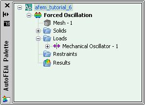
Working with the AutoFEM Palette Window
Working with the "AutoFEM Palette" Window
All problems of the document and their components are shown in the service window "AutoFEM Palette" in the form of the structured tree. This window appears automatically after creating the study. If it is necessary, it can be closed or displayed again with the help of the command:
|
Command Line: |
FEMAPAL |
|
Main Menu: |
AutoFEM | Studies Palette |
|
Icon: |
|

The element "Study" combines all components and objects specified for performing the calculation: finite element mesh ("Mesh"), mechanical loads ("Loads"), constraints ("Restraints").
The folder "Results" is empty until calculation was successfully done.
Solve Study
Step 6: Solve the Study
After constructing the finite element mesh, specifying the loads and restraints, the calculation can be performed.
To solve the problem, the following sequence of steps must be carried out:
1.Invoke the solution's properties window by one of the following methods:
|
Command Line: |
FEMASOLVE |
|
Main Menu: |
AutoFEM | Solve... |
|
Icon: |
|

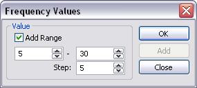
2.On the tab "Parameters", set the option "Frequency values,Hz" and define the range of frequencies (by pressing the button "Add");
3.Set parameters of Rayleigh damping group: the scale factor of mass matrix is equal to 0.02, the scale factor of stiffness matrix is equal to 0.0003.
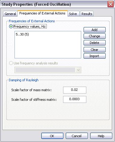
4.Press , to start calculation.
Customizing Results
After successful solution of the Forced Oscillation Analysis problem, we need to analyze the obtained results.
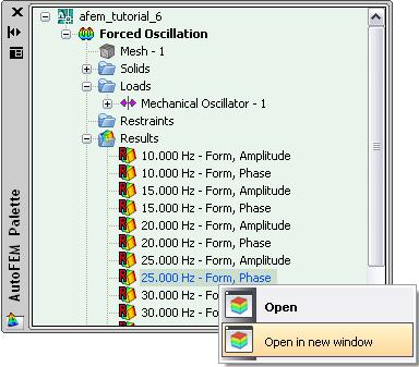
The list of results available for viewing is shown in the problems tree in the folder "Results".
To extend the list of results shown inthe problems tree, the user has to:
1.From the context menu popping up upon pressing on the name of the selected problem, invoke the window for customizing results (command "Results...");
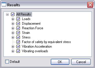
2.Check the results you need;
3.Press .
For viewing a result, select it with in the problems window and select the command "Open in new window". The result will be shown in a new window of the Postprocessor.
Analyze Calculation Results
Step 7: Analyze Calculation Results
Let us analyze some important results: “Form, amplitude, mm”, “Form, phase, deg”. We are going to consider these results for the range of the frequencies and graph result-frequency curves.
Let us pay attention to amplitude-frequency dependence.
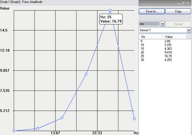
We can see on this diagram that the resonance frequency is about25Hz(to enhance the result a smaller step is needed). To plot points as a smooth curve export the data and paste it to Excel or Mathcad application.
Then let's proceed to phase shift diagram.
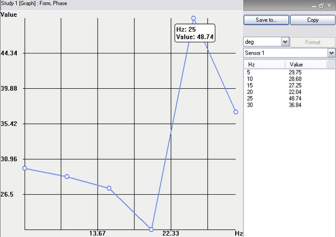
We can see on this diagram that the phase shift (rad) occurs.
Generate Report
Step 8: Generate a Report
The user can create independent of the AutoFEM Analysis electronic documents which include the main information about the solved problem. The report is created in the html- format.
To create a report, the user needs to:
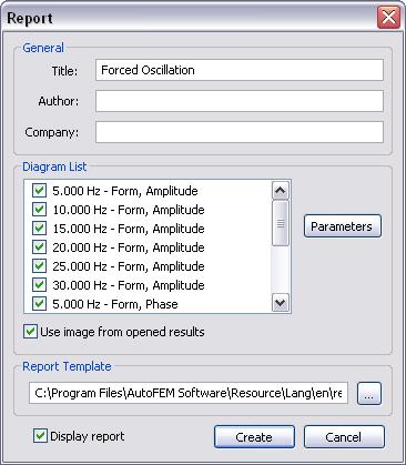
1.Invoke the dialog for customizing a report with the help of the command of the main menu: AutoFEM | Create Report...;
2.Fill in the fields in the group "General";
3.Check the results, which have to be included in the report, in the "Diagram List";
4.Turn on the options "Use image from opened results" and "Display report";
5.Pressing the button  leads to appearance of the dialog for saving the report file.
Congratulations!
You successfully completed the forced oscillation analysis
with the help of the AutoFEM Analysis Lite package.