AutoFEM Buckling Analysis
Using the AutoFEM Buckling Analysis module, mechanical engineers and construction experts who work in the AutoCAD medium are able to carry out calculations of the mechanical stability of the structure. The essence of the stability computation is as follows. Sometimes, mechanical structures which satisfy conditions of strength in the face of static loads may spasmodically collapse when significant forces are applied to this system. This physical phenomenon is usually called “the loss of stability”. Stability calculation is crucial, for instance, for high structures in which forces are directed along them. The Euler’s classical stability calculation implies the determination of the “Factor of Critical Load". This factor is computed for some "trial” and preset mechanical load and allows one to estimate the value of the maximum permissible load on the mechanical system, which, when exceeded, leads to the stability loss. This load is defined as the product of the trial load value and the calculated factor of critical load. Along with the critical load factor, as the result of the stability calculation, the user will obtain the expected form of stability loss, which shows possible deformations of the structure in the case of the loss of stability. If the calculated critical load factor is negative, this means that for the preset load conditions, there will be no stability loss.
In the parameters of the problem of stability one can determine the number of forms of equilibrium states to be determined and other parameters of calculation.
As a result of the buckling analysis, values of the coefficients of the critical loads at which there is loss of stability are obtained, as well as appropriate forms of instability.
The critical load factor means - the estimated value of the coefficient, the product of which on applied load, gives the actual value of the critical load, causing the system to a new equilibrium. For example, the model is applied distributed force 1000 N. Ratio of the critical load of the calculation results was 109.18. This means that the first form of stable equilibrium for this model has a critical load of 109180 N.
The relative displacement (buckling mode) is a shape of the equilibrium steady state corresponding to a certain critical load. Forms of equilibrium states that are displayed in the window Postprocessor after the calculation represent the relative displacement. Analysing these forms you can draw conclusions about the nature of displacement in situations of instability. Knowing the expected equilibrium shape at a certain critical load, one can, for example, specify additional fastening or support in the field of design corresponding to the peak of this form of equilibrium, which would effectively change the mechanical properties of the product.

Forms of equilibrium states corresponding to the fifth and eighth critical loads of construction.
Below you can find some examples of AutoFEM Buckling Analysis
|
Verification Examples of AutoFEM Buckling Analysis |
|
|
|
|
|
|
|
Quick Start on AutoFEM Buckling Analysis
Welcome!
This lesson will help you to perform:
·the Buckling Analysis of the structure subjected to specified loads;
·calculation of the critical load at which the structure looses stability by the AutoFEM Analysis Lite.
You will learn to: create the Buckling Analysis problem;
 create the finite element mesh;
 specify materials;
 specify loads and constraints;
 obtain calculation results in the form of color plots.
Download demo video of the AutoFEM Buckling Analysis Module
Creating Buckling Analysis Study
Step 1: Create the Buckling Analysis Study
Open the example model to start work.
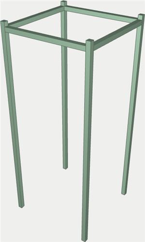
Let us perform the buckling analysis for the structure shown on the picture. The structure is subjected to the force the magnitude of which is 300 kgf (or 2941.995 N).
The equilibrium of the statically loaded structure is called stable if for small perturbations of loads, the structure will experience the small deformations. In certain cases of loading the structure, the stability loss may occur, i.e., the small changes in the applied to the system loads lead to large deformations of the structure, going beyond the linear elasticity theory assumptions.
The loads at which the loss of stability occurs are called critical. In some situations, the critical load may be much smaller than the load at which the structure looses its strength (statical analysis).
To create the Buckling Analysis problem, we need to:
1.Invoke the New problem's properties window using one of the following methods:
|
Command Line: |
FEMASTUDY |
|
Main Menu: |
AutoFEM | Create Study... |
|
Icon: |
|

2.Select the type of the study ( "Buckling Analysis" ) and add to the list ( "Selected Geometry" ) a solid;
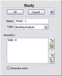
3.Since the option "Generate mesh" is activated, after setting up the problem, the system will automatically proceed to creating finite element mesh;
4. Press  to confirm the New problem creation.
Create Finite Element Mesh
Step 2: Create the Finite Element Mesh
After the problem setup, the system automatically proceeds to creating finite element mesh.
To create manually (or modify) the finite element mesh, we need to carry out the following sequence of steps:
1.Invoke the Mesh's properties window by one of the following methods:
|
Command Line: |
FEMAMESH |
|
Main Menu: |
AutoFEM | Create Mesh... |
|
Icon: |
|

2.Let us build the adaptive mesh. The edge length of an element will be no greater than 14.000 mm
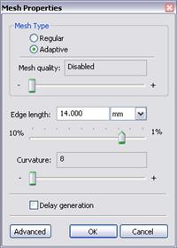
3. Press to complete creating (or modifying) the mesh.
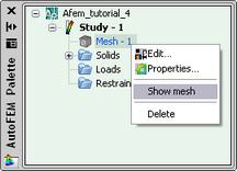
The result of mesh generation is displayed in the 3D window.
Instead of the original model, now you will see the image of the mesh. The original model is not shown at that moment.
In case it is necessary to hide or display again the finite element mesh, choose the element "Mesh" in the service window "AutoFEM Palette" , then invoke the command "Hide Mesh" or "Show Mesh" from the context menu (by pressing  ).
).
Apply Loads
Step 3: Apply Loads
To specify the load "Force", we need to carry out the following sequence of steps:
1.Invoke Load's properties window by one of the following methods:
|
Command Line: |
FEMAFORCE |
|
Main Menu: |
AutoFEM | Loads\Restrains | Force... |
|
Icon: |
|

2.In the properties window of "Force":
a)select faces for load application;
b)specify units and the magnitude of the force (in our case the value is equal to 2941.995 N).
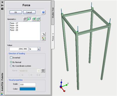
3.Press to confirm load creation.
Create Constraints
Step 4: Define Restraints
To impose constraints on displacements in the directions of the X,Y and Z axes, we need to carry out the following sequence of steps:
1.Invoke the properties window of the Full Restraint by one of the following methods:
|
Command Line: |
FEMAFIX |
|
Main Menu: |
AutoFEM | Loads\Restrains | Fixture... |
|
Icon: |
|

2.In the properties window of the Restraint we need to:
a) select the type of the restraint - fixed ;
b) select the entities to be constrained - faces.
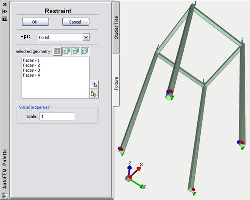
3.Press to confirm the Restraint creation.
Specify Material
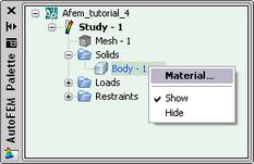
Step 5: Specify Material
For each problem of the finite element analysis, it is important to correctly specify characteristics of the part's material.
To specify (or modify) the material, we need to carry out the following sequence of steps:
1.Invoke the material's properties window by choosing the folder "Solids" in the service window "AutoFEM Palette" and performing the command "Material..."from the context menu (by pressing ).
2.Provide a library of materials (into the group "Library");
3.From the list of materials, select, for example, "Steel AISI 1020";
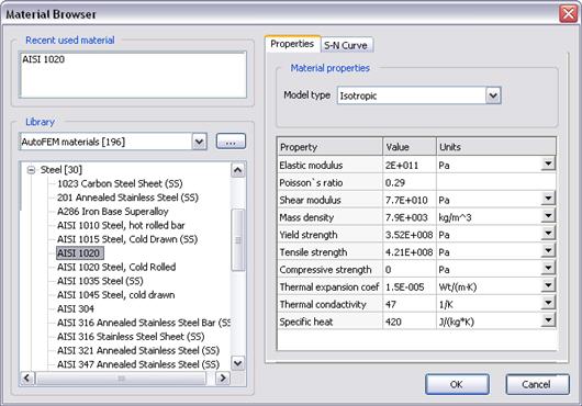
4.Confirm your selection by pressing .
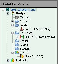
Working with AutoFEM Palette
All problems of the document and their components are shown in the service window "AutoFEM Palette" in the form of the structured tree. This window appears automatically after creating the study. If it is necessary, it can be closed or displayed again with the help of the command:
|
Command Line: |
FEMAPAL |
|
Main Menu: |
AutoFEM | Studies Palette |
|
Icon: |
|

The element "Study" combines all components and objects specified for performing the calculation: finite element mesh ("Mesh"), mechanical loads ("Loads"), constraints ("Restraints").
The folder "Results" is empty until calculation was successfully done.
Solve Study
Step 6: Solve the Study
After constructing the finite element mesh, specifying the loads and constraints, the calculation can be performed.
To solve the problem, the following sequence of steps must be carried out:
1.Invoke the solution's properties window by one of the following methods:
|
Command Line: |
FEMASOLVE |
|
Main Menu: |
AutoFEM | Solve... |
|
Icon: |
|

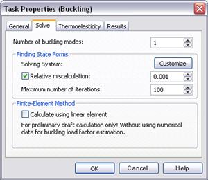
2.On the tab "Solve", for the parameter "Number of buckling modes" select the value 1 (since it is important to find the smallest critical load at which the structure will lose stability);
3.Press , to start calculation.
Customizing Results
After successful solution of the Buckling Analysis problem, we need to analyze the obtained results to draw a conclusion about the probable stability of the structure.
The list of results available for viewing is shown in the problems tree in the folder "Results".
To extend the list of results shown in the problems tree, the user has to:
1.From the context menu popping up upon pressing on the name of the selected problem, invoke the window for customizing results (command "Results...");
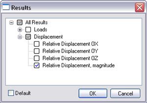
2.Check the results you need;
3.Press .
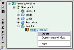
For viewing a result, select it with in the problems window and select the command "Open". The result will be shown in a new window of the Postprocessor.
Analyze Calculation Results
Step 7: Analyze Calculation Results
Analysis of equilibrium state forms
Open the result "Mode 01", corresponding to the smallest critical load.
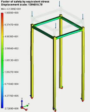
Visually estimate what the deformed state of the structure is like.
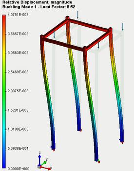
The minimum critical load factor k is positive and larger than 1 (k=" 8.52), "thus, for the given loading conditions, the loss of stability of the structure will not occur. The critical load at which the structure will lose stability can be calculated in the following way: Fcritical =" k * "F, where F - the magnitude of load which is applied to the structure.Thus, the critical load at which the considered structure will lose stability is equal to:Fcritical =" 8.52 * "2941.995 N =" 25065,7974 "N (or 2556 kgf)Analysis of the equilibrium state forms enable us to draw a conclusion about the direction and locations of the maximum displacements corresponding to the critical load. This information can be used for optimization of the structure to improve its stability Next, for the given structure we need to perform the calculation of the static strength (see Lesson 1). The structure is subjected to the same force of magnitude 2941.995 N, as that for buckling analysis. Constraints (restraints) for the structure were not modified as well. From the results of calculation, we see that for given loads the structure is statically robust (factor of safety by equivalent stress is greater than 1).
Report
Step 8: Generate a Report
The user can create independent of the AutoFEM electronic documents which include the main information about the solved problem. The report is created in the html- format.
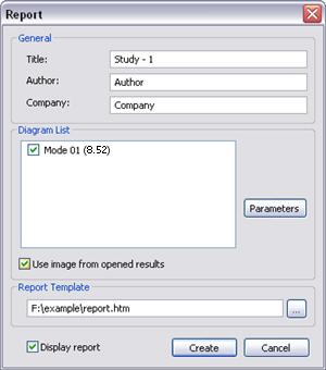
To create a report, the user needs to:
1.Invoke the dialog for customizing a report with the help of the command of the main menu: AutoFEM | Create Report...;
2.Fill in the fields in the group "General";
3.Tick the results, which have to be included in the report, in the "Diagram List";
4.Turn on the options "Use image from opened results" and "Display report";
5.Pressing the button  leads to appearance of the dialog for saving the report file.
Congratulations!
You successfully carried out the buckling analysis of the structure by the AutoFEM Analysis Lite.